Offroad Trailblazers and Envoys

Author Archives: Trail X

Front Axle 4WD Disconnect Rebuild

Theory of operation, common failures, and rebuilding:


schematic-1


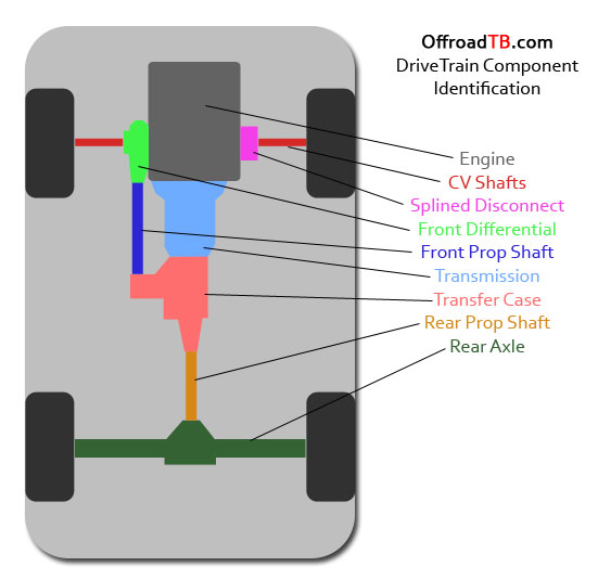
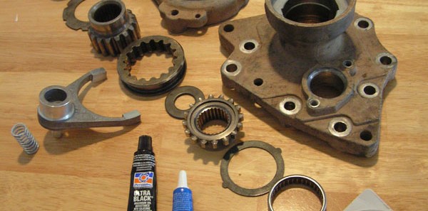
Unit 56, above, is known as the front axle 4WD disconnect.  It resides on the passenger side of the oil pan, opposite of the front differential. The disconnect allows the front left and right wheels to spin independently of each other, and allows the front prop-shaft to remain still while in 2WD mode.  This helps to prevent the front differential and prop-shaft seals from wearing, and theoretically reduces the rolling resistance of the drive train to improve the fuel mileage. Here is an actual picture of the parts involved with the 4WD actuator:
 
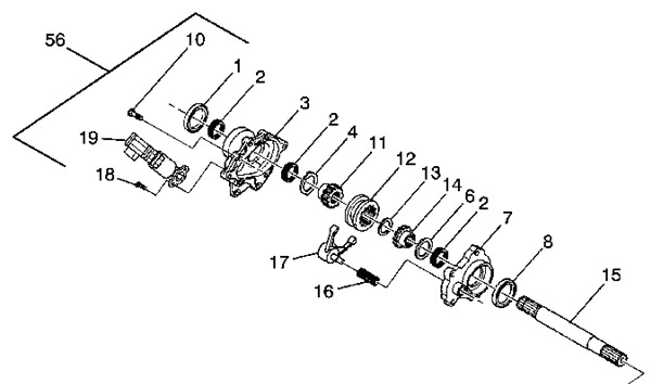
  The internal parts are as follows, referencing the parts from the picture above:
 
Part GM Part Number Description
1 12479302 Outer CV Shaft Seal
2 26053326 Needle Bearing (3 used)
3 12479081 or 12479197 Outer Housing
4 12471625 Outer Thrust Washer
11 12471628 Outer Gear (CV Shaft Gear)
12 26036092 Gear Shift Collar (or sleeve)
17 12479132 Shift Fork
16 12471624 Fork Spring
13 12471629 Middle Thrust Washer
14 12471627 Inner Gear (Intermediate Shaft Gear)
6 12471623 Inner Thrust Washer
7 12471633 Inner Housing
8 15801507 Inner Shaft Seal
19 12471631 Front 4WD Actuator

Below I show a partially-assembled unit to show the operation.  When in 2WD mode, the shift fork is forced into the position below by the spring (not pictured) that seats over the fork’s pin.  The fork is engaged with the collar, which rides only on the outer gear (the bottom gear here).  This allows the inner and outer gears to spin independently.
 
  When in A4WD, 4HI, and 4LO, the disconnect is in the position below.  The actuator pushes on the outside cup of the fork (shown here by the spacer below the fork) and overcomes the force of the fork’s spring.  The fork then slips into the position shown below, pushing the collar over to engage both the inner and outer gears.  This locks the left and right wheel shafts together.
 
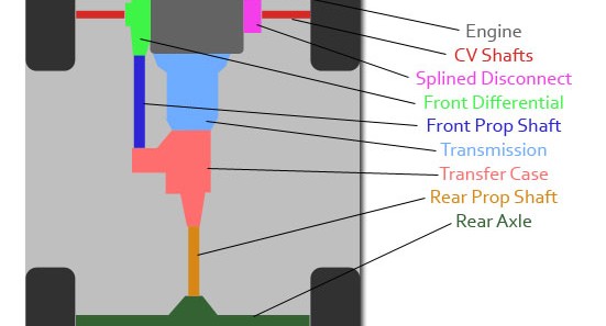
  Because the gears are not always aligned, it is possible for the shift collar to slide over, but not engage with the inner gear.  This is due to the gears not exactly meshing.  Due to this, it’s recommended to only shift into A4WD, 4HI, and 4LO when stopped.  Then, creep forward and turn the steering wheel left and right.  You’ll know when 4WD engages, as it will be harder than normal to turn the steering wheel, or you may feel some wheel hop. Below is a schematic of the actuator.  It’s a view from the bottom when cut in half as it’s mounted on the vehicle (assuming it is in 4WD mode).
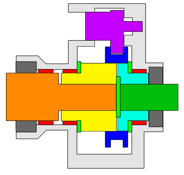
schematic-2      
Color Part
Orange Input CV Shaft
Dark Green Intermediate Shaft
Light Green Thrust Washers
Red Bearings
Yellow Outer Gear
Light Blue Inner Gear
Dark Blue Shift Collar
Purple Shift Fork
Dark Grey Shaft Seals
Light Grey Aluminum Housings

So how and why does this fairly simple assembly fail?

It seems the most common failure is the drying out of the grease.  This is most likely due to the outer seal failing.  When the grease in the outer bearing begins to dry up, the bearing can seize.  This causes the bearing to either spin, or be crushed (in the case of a lifted vehicle).  This failure mode seems to almost always begin with the outer bearing.  Often if can be characterized by a rattle at low speeds and excessive play in the CV shaft connection.  Below shows a comparison between a new bearing and one that has been worn excessively due to a seal failure.
 
  The second common failure is with the shift fork itself fracturing.  This is assumed to be caused due to engagement of the 4WD system while at high speeds.  The shift collar engages on the gear, but due to the high speeds of the gears, the fork hangs on the collar, and is sheared.  This may be partially due to the fork’s material, which is aluminum.  This failure is harder to spot without opening the case, however if your disconnect doesn’t connect, or doesn’t disconnect, this could by your failure mode.


How do I rebuild the disconnect?

The first step is removing the disconnect from the vehicle. To do this, you have to take the suspension apart.
  1. Lift front of vehicle and properly stabilize
  2. Remove passenger front wheel
  3. Un-clip wheel sensor wire (3 places)
  4. Remove brake line holder from knuckle
  5. Remove CV axle nut (35 mm)
  6. Tap end of CV axle to remove from wheel bearing
  7. Remove (or cut off) end link
  8. Remove upper ball joint from upper control arm
  9. Remove nuts from upper strut mount
  10. Gently pull down on knuckle to attain room to entirely remove wheel end of CV axle from wheel bearing
  11. Remove oilpan skidplate
  12. Use a drift against the back of the CV tripod housing and hammer to remove from disconnect (you may need a large sledge hammer)

  At this point, you have removed the CV shaft from the disconnect, however if you haven’t don’t worry.  When I went to hammer out my CV shaft, the shaft would only rattle around due to the crushed bearings.  Instead, I just removed the entire disconnect and shaft at the same time.  The shaft can be removed after you remove the disconnect. The disconnect is simple to remove, however can get somewhat stuck in the tight fit between the oil pan and the disconnect housing.  Pry on the housing to remove the disconnect.  It may take some muscle. Note, when the intermediate shaft is unsupported, as in the picture below, the vehicle should not be driven faster than a crawl.  The intermediate shaft will otherwise bounce around in the oil pan and destroy itself and the oil pan. Also of note: my 2005 had no problems here, but I understand that prior years ran the transmission fluid cooling lines (shown to the top left of the image below) over the top left bolt.  These need to be moved before removing the disconnect.
 
  Disconnect and CV shaft removed together.
 
  Once the disconnect was cracked, I could see the grease was very black, signaling that there is significant wear present.  Notice the shift fork is not engaging the collar anymore due to wear.
 
  Once the parts are clean, inspect everything for wear.  If your gears show wear on the bearing surface, you  need to replace them, otherwise all your hard work will only lead to premature bearing wear and failure.
 
  The first step to the reassembly is pressing in the new bearings.  First seat the bearings by hand and apply a light bead of red locktite to the exterior of the bearing.
 
  Lightly hammer the bearing into place using a star pattern, similar to when you’re tightening lug nuts.  Be sure to hammer the bearing in flat.  Wipe away any excess locktite, you don’t want it seeping into the bearing.
 
  Once all three bearings are press into place, install the seals (not pictured here).  The seals will install in a similar method to the bearings, however a peice of wood should be used between the hammer and the seal.  Do not hammer the seal. It’s now time to begin greasing and assembling.  I used Mobil 1 synthetic grease for it’s wide temperature range, wear protection under heavy loads, and resistance to water wash. Begin by working liberal amounts of grease into the needle bearings.
 
  Next, begin buttering the wear surfaces of every part, and installing them into place.
 
  Be sure to cover all wear surfaces, including the finger and outer ‘shank’ of the fork.
 
  Meticulously place the parts, don’t forget anything:
 
  After everything is in place, add more grease to  any void areas. Be careful not to over-fill, as that can cause issues too.
 
  Clean up the gasket surfaces and apply RTV.  I used ultra black RTV.
 
  Bring the halves together, and ensure everything connects properly.  Be sure to test the fork and ensure it works (the spring really isn’t that strong).
 
  Tighten down the bolts.
 
  Install the disconnect to the oil pan, install the CV shaft, and re-connect the suspension components.
 
  Time to test it all and ensure it works.

Conclusions:

The disconnect does have some potential issues, luckily there are some techniques to preventing these failures.  First, engage 4WD when traveling at slow speeds.  Second, check the outer seal and CV tripod for wear or excess movement.  If you check this problem early enough, you can save a lot of the parts from extra wear.

UPDATE (Mar 28, 2013):

Many of us have found (despite proper greasing and service of the assembly) that the extra bending load from a lifted CV shaft will still tend to fail the outside bearings quicker than we would prefer. The current best-case fix seems to be from removing items 11, 12, 13, 14, 16, and 17 (reference the top schematic in this article) and replacing them with GM part # 12471636, Sleeve, Front Drv Axle (reference item 5, below) from the AWD variant of the disconnect. The only down side is that it could equate to poorer gas mileage and faster wear on your front differential.
      AWD-Sleeve

Trail Rating Guide

The following trail rating system is intended only as a guide. The one factor that can never be rated is driver experience. The ratings below assume a driver with a good knowledge of their vehicle’s capabilities and dimensions, line selection, and basic accident avoidance techniques like left foot braking, correcting for a skid, throttle control, and threshold braking. This guide does not replace common sense and personal responsibility.
For the purposes of this guide, and as a reference for this website as a whole, the following terms are defined as follows:

Road

Frequently graded and wide, with moderate grades and good traction surface.

Track

Infrequently graded and will be narrow, with fewer places for passing. Typically requires AWD and some clearance.

Trail

May never have been graded. Requires high clearance SUV or truck with low range gearing.
 

TRAIL RATINGS


1

Improved/Graded Dirt Road

Passable by most standard vehicles, excluding those with low hanging body panels or that are designed for on-road sport driving with ultra low ride and tire section height.

1.5

Graded Dirt Road

Still passable by most 2WD vehicles. However, caution is required and lower speeds may be necessary for vehicles with less clearance. Small rocks (less than 5″) may be embedded in road surface. Sufficient room for passing on most of the road. Some steep grades possible. AWD required if road is wet or icy.

2

Formed Track

Not passable by standard passenger vehicles. High clearance preferred, AWD preferred. Steep grades present, larger rocks embedded in trail (less than 7″). Some loose trail surfaces and shallow water crossings possible. A spotter may be required on the most challenging portions to prevent body damage on vehicles with less clearance. Sand and dry washes may challenge available traction requiring lower air pressure on some vehicles. Trail may be narrow and require backing to allow other vehicles to pass.

2.5

Rugged Track

Not suitable for 2WD vehicles, or low clearance cross over vehicles. AWD required, low range gearing preferred. Rutted, crossed axle terrain possible, with loose, steep climbs required. Deep sand possible. Some rock crawling possible on loose rocks up to 8″ in diameter. Some larger rocks may be present, possibly requiring a spotter to negotiate. Small ledges possible, with larger embedded rocks present. Water crossing to 12″ possible. Loose surfaces will be present, with tight clearance, smaller margin for error, and the possibility of body damage. Within the capability of any high clearance stock SUV or truck. AWD cross-over vehicles will struggle and may suffer damage due to lack of low range gearing.

3

Formed Trail

High Clearance SUV or Truck required with low range gearing. Trail will be very rough and heavily eroded, with large, loose rocks present and steep, loose climbs requiring good traction and driver skill to negotiate. Wheel placement critical. Skid plates required, along with larger tires (31″+) necessary to prevent damage. Deeper water and mud crossings possible. Parts of the trail may be entirely in a wash, with loose sand and large rocks present. Possibility of rock ledges, and severe crossed axle obstacles. Good suspension articulation required to maintain traction. Rear limited slip differential or traction control system recommended to limit trail and vehicle damage.

3.5

Rugged Trail

High clearance SUV or truck required, taller suspension and tires recommended. Few stock vehicles capable of completing the trail without damage. Very large rocks exceeding 12″ present throughout trail requiring a spotter or heavily modified vehicle to traverse. Very loose and cambered climbs present, also heavily rutted requiring good suspension travel. Tall ledges present requiring good clearance or rocker panel protection. Little margin for error, and possibility of body damage. Tires must be 31″+ with aggressive tread and strong sidewalls. Lower tire pressure, skid plates, and limited slip or traction control required to prevent vehicle or trail damage. Rear locking differential and 32″+ tires recommended.

4

Challenging Trail

High clearance modified vehicle required. Not within the capability of a stock vehicle without damage. Trail likely in river or wash bottom with very large rocks present. Deep mud possible requiring aggressive tires and higher speeds. Water crossings in excess of 24″ possible. Heavily rutted and crossed axle terrain present, with large ledges and very steep hills with embedded and loose rocks. Body protection required to prevent damage, with good skid plates and stronger (or spare) steering components necessary. Winching and extraction possible. 32″ tires, rear locking differential and flexible suspension required. 33″ tires and front locking differential recommended.
In general, the following trails are outside the scope of this website.

4.5

Extreme Trail

Heavily modified vehicle required. Extreme rock crawling, with very large ledges present requiring winching for shorter wheelbase (SWB) vehicles. Body and drivetrain damage likely. Very cambered terrain may cause rollovers. Water crossings may be hood high, and mud will be very deep and heavily rutted. Vehicles will require heavy modifications. 33″+ tires required, along with front and rear locking differentials in upgraded axles. 35-37″ tires recommended. Winch required on SWB vehicles. Roll cages or full metal roof required. Driver must be experienced.

5

No Trail!

Custom vehicle, very experienced driver required. Competition-level vehicles on insane terrain with frequent rollovers and drivetrain damage. Full custom vehicles with massive axles, 37″+ tires, cutting brakes, very low gears, 1-ton drivetrain, and custom chassis.
These ratings have been adopted from the ranking list created by the editors of Overland Journal. http://www.overlandjournal.com/overlanding/trail_rating_guide/

Vehicle Recovery

Understanding the basics:

A lot of people make the mistake of just pulling out a winch line, wrapping it around a tree, and powering the winch in. No, no, no. That may get you unstuck, but it’s risky and can be dangerous. There are proper methods and proper steps that should be followed that can reduce the risks inherent to off road vehicle recovery. I’ll take you through the process step by step in the following article. Before proceeding with any recovery steps or tactics, the basics need to be discussed. The most basic thing to understand is that any recovery process creates large loads through the equipment that is in the system (‘the system’ refers to any component in use during the recovery, including the vehicles and anchor points). An important thing to understand is the WLL, or working load limit, of the equipment. By understanding the loads that the system can possibly experience, and exceeding those limits with the strength of the components in the system, you increase your safety factor. A safety factor is the breaking strength of the weakest component of the system, divided by the force being exerted on that component. A high safety factor is desired to ensure that no breakage can occur. All good recovery equipment has WLLs labeled on them, or at least on their packaging. Some components are labeled in tons, some in kilograms, and some in pounds. Make sure you know the conversions between the units and understand your weakest link. You often want to design your system so the weakest link is the pulling mechanism (you or a motor). If your pulling component isn’t the weakest link, it is actually possible to fail a component in the system. The weakest component in the system is known as the ‘fuse’. It’s important to understand how the forces transfer, not only through the recovery equipment, but also through the vehicle. Make sure the recovery points on the vehicle can withstand the forces involved in a recovery situation, and that they can transmit the forces to the frame. Even then, make sure you understand where the stuck-forces are coming from. If you have a vertical rock face in front of one of your tires, a recovery force could end up bending your tie-rod before moving the vehicle. It’s also important to understand the three main categories of recovery.
  • Static – not putting impulse loads on the system: winching
  • Dynamic – recovery by momentum: yanker rope, snatch strap
  • Passive – use of traction aids, not inducing horizontal loads on the vehicle
A static recovery loads the recovering system without any stretching component. The recovery force is derived from a positive displacement element, such as a winch, or hand ratchet. Dynamic elements, such as ‘snatch’ straps, should not be used in a static recovery unless it is a last resort. A dynamic recovery can be useful for a quick recovery, provided you have a second vehicle present. The recovery force is derived from the other vehicle’s momentum. If a dynamic strap is not used in this type of recovery, extreme damage can result. A passive recovery does not utilize horizontal forces at all to recover the vehicle. The recovery is performed by simply increasing the wheel traction through various methods. These three methods will be covered in depth on the coming pages. Lastly… whenever a vehicle gets stuck or needs aid, remember Bill Burke’s 3 Ps before performing any recovery. Patience, Plan, then Practice. I’ve adapted the 3 Ps into the following four steps:
  • Assess
  • Plan
  • Envision
  • Perform
These steps and much more are covered on the following pages in the Recovery Section, so read on to the other articles!

Article References

Brady, Scott. “Road to Recovery.” Overland Journal Summer 2009: 41-51. Burke, Bill, host. Getting UNStuck. Dir. Gregory Hren. DVD. Greg Hren Photography, 2003. Elfstrom, Bruce. “Skills: Winching Without the Worry.” Overland Journal Spring 2009: 105-116. Sheppard, Tom. Four-by-Four Driving. Hertfordshire, England: Desert Winds Publishing, 2006.

Transmission Technical Documents – 4L60e

Through my research I’ve run across a few very helpful documents regarding the trailblazer transmission (the 4L60e).  I’ve amassed them here.

Electronic Controls Document:

Details of the internal wiring, pin-outs, and other electronic details. electronic controls

Hydraulic Schematic:

(Left is the key document, right is the actual schematic file) Details of the internal hydraulic routing and their functions. schematic key hydraulic schematic

Transmission Overhaul Detail:

Factory detail of a complete transmission overhaul. overhaul

Conversion to Manual Shift:

An interesting article detailing how to convert an eletronically controlled 4L60e into a manually-shifted transmission. manual shifting

Diagnosing the 4WD System

We run into many questions where the owner realizes the front tires are not engaging when in a 4WD mode. The first and easiest step is to check for the appropriate sounds from your system.  With the engine off, but the key in the accessory position, switch the 4WD switch from 2HI to 4HI.  You should hear two distinct electric motors activate.  The first is a high-pitched whine that lasts approximately 2 seconds.  This sound should emanate from the front passenger wheel-well, it is the front axle actuator.  The second sound is a lower-pitched motor that operates quickly (maybe 1/3 second).  This sound comes from the encoder motor on the side of the transfer case, under the center of the vehicle.  If you do not hear one of the sounds, that should be a clue of where the issue is coming from.  Usually an inactive motor will be coupled with a “service 4WD light”. 
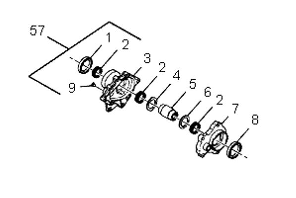
If you believe your front tires are not receiving power when in 4HI or 4LO, and the “service 4WD light” is not illuminated, follow the flowchart to the right. Please ensure to park on level ground, place the vehicle in park, and properly chock your tires before performing the diagnostic check. Even if the flowchart points to a particular system as the culprit, there could be other variables interfering with the diagnosis. The flowchart only gives you a best initial guess.
For instance, one individual reported no 4WD and the flowchart pointed towards the disconnect, however the actual issue was that the CV shaft had popped out of engagement with the front differential. Luckily he found this after a cursory check of all driveline components.
ORTB.com has articles written on the following systems: Since terminology can sometime be different among websites and individual experiences and backgrounds, we have also drawn up the following locator for the drivetrain components of the trailblazer.  (Drawn viewed from above the vehicle.)