Theory of operation, common failures, and rebuilding:
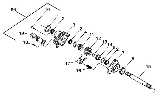
Unit 56, above, is known as the front axle 4WD disconnect. It resides on the passenger side of the oil pan, opposite of the front differential. The disconnect allows the front left and right wheels to spin independently of each other, and allows the front prop-shaft to remain still while in 2WD mode. This helps to prevent the front differential and prop-shaft seals from wearing, and theoretically reduces the rolling resistance of the drive train to improve the fuel mileage. Here is an actual picture of the parts involved with the 4WD actuator:
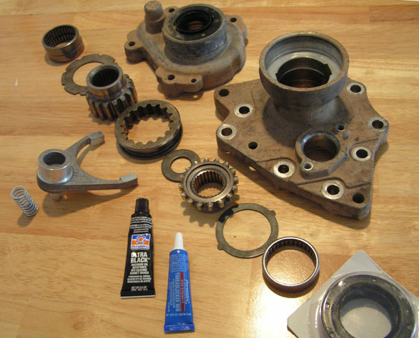
The internal parts are as follows, referencing the parts from the picture above:
| Part | GM Part Number | Description |
| 1 | 12479302 | Outer CV Shaft Seal |
| 2 | 26053326 | Needle Bearing (3 used) |
| 3 | 12479081 or 12479197 | Outer Housing |
| 4 | 12471625 | Outer Thrust Washer |
| 11 | 12471628 | Outer Gear (CV Shaft Gear) |
| 12 | 26036092 | Gear Shift Collar (or sleeve) |
| 17 | 12479132 | Shift Fork |
| 16 | 12471624 | Fork Spring |
| 13 | 12471629 | Middle Thrust Washer |
| 14 | 12471627 | Inner Gear (Intermediate Shaft Gear) |
| 6 | 12471623 | Inner Thrust Washer |
| 7 | 12471633 | Inner Housing |
| 8 | 15801507 | Inner Shaft Seal |
| 19 | 12471631 | Front 4WD Actuator |
Below I show a partially-assembled unit to show the operation. When in 2WD mode, the shift fork is forced into the position below by the spring (not pictured) that seats over the fork’s pin. The fork is engaged with the collar, which rides only on the outer gear (the bottom gear here). This allows the inner and outer gears to spin independently.

When in A4WD, 4HI, and 4LO, the disconnect is in the position below. The actuator pushes on the outside cup of the fork (shown here by the spacer below the fork) and overcomes the force of the fork’s spring. The fork then slips into the position shown below, pushing the collar over to engage both the inner and outer gears. This locks the left and right wheel shafts together.

Because the gears are not always aligned, it is possible for the shift collar to slide over, but not engage with the inner gear. This is due to the gears not exactly meshing. Due to this, it’s recommended to only shift into A4WD, 4HI, and 4LO when stopped. Then, creep forward and turn the steering wheel left and right. You’ll know when 4WD engages, as it will be harder than normal to turn the steering wheel, or you may feel some wheel hop. Below is a schematic of the actuator. It’s a view from the bottom when cut in half as it’s mounted on the vehicle (assuming it is in 4WD mode).
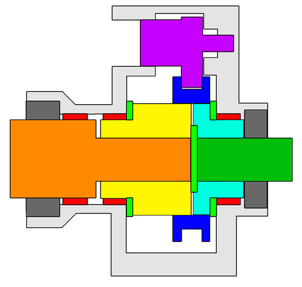
| Color | Part |
| Orange | Input CV Shaft |
| Dark Green | Intermediate Shaft |
| Light Green | Thrust Washers |
| Red | Bearings |
| Yellow | Outer Gear |
| Light Blue | Inner Gear |
| Dark Blue | Shift Collar |
| Purple | Shift Fork |
| Dark Grey | Shaft Seals |
| Light Grey | Aluminum Housings |
So how and why does this fairly simple assembly fail?
It seems the most common failure is the drying out of the grease. This is most likely due to the outer seal failing. When the grease in the outer bearing begins to dry up, the bearing can seize. This causes the bearing to either spin, or be crushed (in the case of a lifted vehicle). This failure mode seems to almost always begin with the outer bearing. Often if can be characterized by a rattle at low speeds and excessive play in the CV shaft connection. Below shows a comparison between a new bearing and one that has been worn excessively due to a seal failure.
The second common failure is with the shift fork itself fracturing. This is assumed to be caused due to engagement of the 4WD system while at high speeds. The shift collar engages on the gear, but due to the high speeds of the gears, the fork hangs on the collar, and is sheared. This may be partially due to the fork’s material, which is aluminum. This failure is harder to spot without opening the case, however if your disconnect doesn’t connect, or doesn’t disconnect, this could by your failure mode.

How do I rebuild the disconnect?
The first step is removing the disconnect from the vehicle. To do this, you have to take the suspension apart.- Lift front of vehicle and properly stabilize
- Remove passenger front wheel
- Un-clip wheel sensor wire (3 places)
- Remove brake line holder from knuckle
- Remove CV axle nut (35 mm)
- Tap end of CV axle to remove from wheel bearing
- Remove (or cut off) end link
- Remove upper ball joint from upper control arm
- Remove nuts from upper strut mount
- Gently pull down on knuckle to attain room to entirely remove wheel end of CV axle from wheel bearing
- Remove oilpan skidplate
- Use a drift against the back of the CV tripod housing and hammer to remove from disconnect (you may need a large sledge hammer)

At this point, you have removed the CV shaft from the disconnect, however if you haven’t don’t worry. When I went to hammer out my CV shaft, the shaft would only rattle around due to the crushed bearings. Instead, I just removed the entire disconnect and shaft at the same time. The shaft can be removed after you remove the disconnect. The disconnect is simple to remove, however can get somewhat stuck in the tight fit between the oil pan and the disconnect housing. Pry on the housing to remove the disconnect. It may take some muscle. Note, when the intermediate shaft is unsupported, as in the picture below, the vehicle should not be driven faster than a crawl. The intermediate shaft will otherwise bounce around in the oil pan and destroy itself and the oil pan. Also of note: my 2005 had no problems here, but I understand that prior years ran the transmission fluid cooling lines (shown to the top left of the image below) over the top left bolt. These need to be moved before removing the disconnect.

Disconnect and CV shaft removed together.

Once the disconnect was cracked, I could see the grease was very black, signaling that there is significant wear present. Notice the shift fork is not engaging the collar anymore due to wear.

Once the parts are clean, inspect everything for wear. If your gears show wear on the bearing surface, you need to replace them, otherwise all your hard work will only lead to premature bearing wear and failure.

The first step to the reassembly is pressing in the new bearings. First seat the bearings by hand and apply a light bead of red locktite to the exterior of the bearing.

Lightly hammer the bearing into place using a star pattern, similar to when you’re tightening lug nuts. Be sure to hammer the bearing in flat. Wipe away any excess locktite, you don’t want it seeping into the bearing.

Once all three bearings are press into place, install the seals (not pictured here). The seals will install in a similar method to the bearings, however a peice of wood should be used between the hammer and the seal. Do not hammer the seal. It’s now time to begin greasing and assembling. I used Mobil 1 synthetic grease for it’s wide temperature range, wear protection under heavy loads, and resistance to water wash. Begin by working liberal amounts of grease into the needle bearings.

Next, begin buttering the wear surfaces of every part, and installing them into place.

Be sure to cover all wear surfaces, including the finger and outer ‘shank’ of the fork.

Meticulously place the parts, don’t forget anything:

After everything is in place, add more grease to any void areas. Be careful not to over-fill, as that can cause issues too.

Clean up the gasket surfaces and apply RTV. I used ultra black RTV.

Bring the halves together, and ensure everything connects properly. Be sure to test the fork and ensure it works (the spring really isn’t that strong).

Tighten down the bolts.

Install the disconnect to the oil pan, install the CV shaft, and re-connect the suspension components.

Time to test it all and ensure it works.
Conclusions:
The disconnect does have some potential issues, luckily there are some techniques to preventing these failures. First, engage 4WD when traveling at slow speeds. Second, check the outer seal and CV tripod for wear or excess movement. If you check this problem early enough, you can save a lot of the parts from extra wear.UPDATE (Mar 28, 2013):
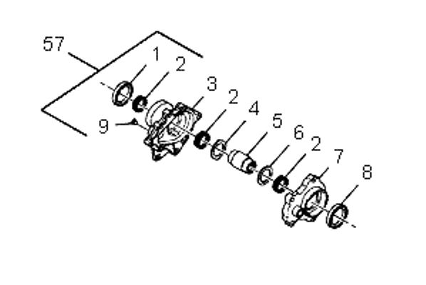
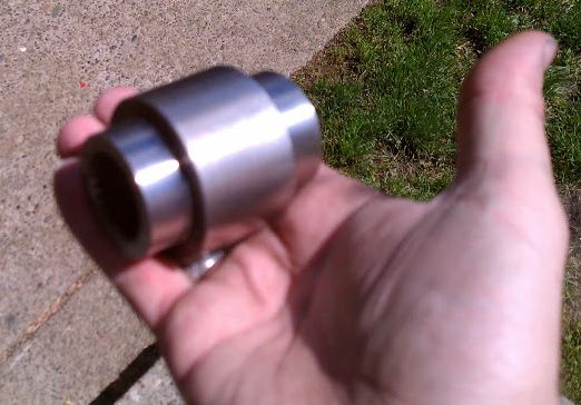
Many of us have found (despite proper greasing and service of the assembly) that the extra bending load from a lifted CV shaft will still tend to fail the outside bearings quicker than we would prefer. The current best-case fix seems to be from removing items 11, 12, 13, 14, 16, and 17 (reference the top schematic in this article) and replacing them with GM part # 12471636, Sleeve, Front Drv Axle (reference item 5, below) from the AWD variant of the disconnect. The only down side is that it could equate to poorer gas mileage and faster wear on your front differential.