- 9/32” or 7mm Socket/Ratchet or Nut Driver
- ¼” Socket and ¼” Drive Ratchet
- Wire Strippers
- Soldering Iron
- Solder
- Heat Shrink (medium and small sizes)
- Electrical Tape
- Dremel or Round Hand File
- Heat Gun (or Lighter, in a pinch)
 Step 2:
Lift hood, and either disconnect battery, or unplug fuse labeled “ELEC BRK (30A)”. On my ’07 5.3L, it is Fuse 19 in the under-hood fuse box.
Step 3:
Remove lower kick-panel from under dash. There is a screw on either side, as shown, and a clip in the middle. After you remove the screws, just pull straight down on the side of the panel closest to you. I used a 7mm or 9/32” socket for the screws.
Step 2:
Lift hood, and either disconnect battery, or unplug fuse labeled “ELEC BRK (30A)”. On my ’07 5.3L, it is Fuse 19 in the under-hood fuse box.
Step 3:
Remove lower kick-panel from under dash. There is a screw on either side, as shown, and a clip in the middle. After you remove the screws, just pull straight down on the side of the panel closest to you. I used a 7mm or 9/32” socket for the screws.
 Step 4:
Find the (4) wires connected to the main wiring harness on the left side of the foot well, as shown. Pull them from the electrical tape on the main harness, and take the electrical tape off of the ends of the wires.
Step 4:
Find the (4) wires connected to the main wiring harness on the left side of the foot well, as shown. Pull them from the electrical tape on the main harness, and take the electrical tape off of the ends of the wires.
 Here is where the paths split. Some of you will use the crimping butt-connectors that came with the unit, but I will never use butt-connectors on something as important as stopping something that weighs more than my vehicle. On anything where anyone’s life can be put in danger by a corroded connection, I ALWAYS solder and heat-shrink EVERYTHING! The following steps are for the “soldering” path. If you choose to do otherwise, that is your choice to make.
Step 5:
Remove the wire ties and labels from the connector and pigtail that came with the brake controller unit, and slide appropriately sized heat shrink up the wires. You will want to be sure to put the heat shrink far enough away from the solder joints that it does not get accidentally shrunk while you are soldering.
Here is where the paths split. Some of you will use the crimping butt-connectors that came with the unit, but I will never use butt-connectors on something as important as stopping something that weighs more than my vehicle. On anything where anyone’s life can be put in danger by a corroded connection, I ALWAYS solder and heat-shrink EVERYTHING! The following steps are for the “soldering” path. If you choose to do otherwise, that is your choice to make.
Step 5:
Remove the wire ties and labels from the connector and pigtail that came with the brake controller unit, and slide appropriately sized heat shrink up the wires. You will want to be sure to put the heat shrink far enough away from the solder joints that it does not get accidentally shrunk while you are soldering.
 Step 6:
Solder wires in the appropriate order as follows:
Step 6:
Solder wires in the appropriate order as follows:
Wire Color Chart |
||
|
GMT 360 Color |
Tekonsha Color |
Usage |
|
RED |
BLACK |
BATTERY + |
|
DARK BLUE |
BLUE |
TO TRAILER BRAKES |
|
BLACK |
WHITE |
GROUND |
|
LIGHT BLUE |
RED |
STOPLIGHT |
 Step 7:
When wires have cooled, slide heat shrink over bare wires, and shrink it using a heat gun.
Step 7:
When wires have cooled, slide heat shrink over bare wires, and shrink it using a heat gun.
 At this point, after the heat shrink has been applied, reconnect the battery cable or put the fuse back in, plug the connector into the brake controller, and make sure it turns on and says “trailer not connected” when you press the brake pedal. If it works, proceed to the next step.
Step 8:
Wrap entire loom in electrical tape, to keep wires from getting separated and caught on anything.
At this point, after the heat shrink has been applied, reconnect the battery cable or put the fuse back in, plug the connector into the brake controller, and make sure it turns on and says “trailer not connected” when you press the brake pedal. If it works, proceed to the next step.
Step 8:
Wrap entire loom in electrical tape, to keep wires from getting separated and caught on anything.
 Step 9:
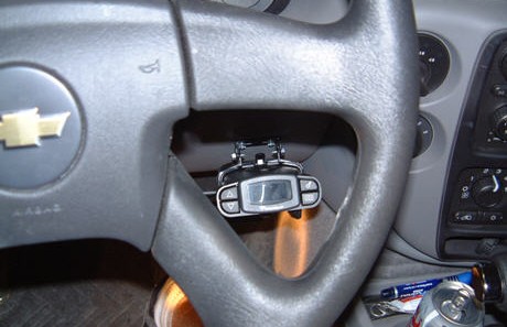
Pick a suitable place to mount the unit. I like to be able to see the unit through the steering wheel, without having to move my head.
Use the ¼” socket or nut driver and fasten the mounting bracket onto the dash, using the supplied self-tapping screws.
NOTE: If using any kind of inertia-style brake controller, like the Prodigy or P3, be sure the bracket is horizontal, and the unit will be facing directly into the direction of travel. These cannot be mounted sideways. The picture does not look like it, but the controller is mounted roughly level, in the direction of travel.
Use the ¼” socket on the ¼” drive ratchet to secure the mounting bracket to the P3 mounting clip, using the supplied self-tapping screws.
Step 9:
Pick a suitable place to mount the unit. I like to be able to see the unit through the steering wheel, without having to move my head.
Use the ¼” socket or nut driver and fasten the mounting bracket onto the dash, using the supplied self-tapping screws.
NOTE: If using any kind of inertia-style brake controller, like the Prodigy or P3, be sure the bracket is horizontal, and the unit will be facing directly into the direction of travel. These cannot be mounted sideways. The picture does not look like it, but the controller is mounted roughly level, in the direction of travel.
Use the ¼” socket on the ¼” drive ratchet to secure the mounting bracket to the P3 mounting clip, using the supplied self-tapping screws.
 Step 10:
Use the Dremel or file to take the front of the plastic on the kick panel, off, to leave a place for the wires to go into the dash area, and not get pinched.
I put the cutout right where the indent is for the knee panel to mount.
Step 10:
Use the Dremel or file to take the front of the plastic on the kick panel, off, to leave a place for the wires to go into the dash area, and not get pinched.
I put the cutout right where the indent is for the knee panel to mount.
 Step 11:
Using the screws you took out earlier, use the 9/32” nut driver or socket to put the lower kick panel back into position, being careful to route the wires into the cutout you just created, and that they don’t pinch.
Make sure the unit is working by plugging in an empty trailer and using the trailer brakes.
Step 11:
Using the screws you took out earlier, use the 9/32” nut driver or socket to put the lower kick panel back into position, being careful to route the wires into the cutout you just created, and that they don’t pinch.
Make sure the unit is working by plugging in an empty trailer and using the trailer brakes.
 That’s it. You’re done.
