I recently had a vibration problem in my 03 LS that didn’t go away after I replaced u-joints, balanced the tires, and checked the front wheel uni-bearing hubs (which were previously replaced). I also noticed a squeak and at times a rumble that seemed to be coming from the general direction of the rear axle — especially easy to hear while driving next to a wall with the windows open.
All this led me to investigate the rear axle bearings for wear. Note that I have trailered heavily with my TB, often pulling as much as 8000 pounds when transporting my off-road truck. That sort of use — with a vehicle sometimes on the bump stops with the load — is conducive to rear axle bearing wear.
I discovered that the bearings on both sides of the rear axle were worn. Clues to the wear — apart from the symptoms listed above — are burnt spots (brown color) on the areas where the bearings ride on the axle shafts. I’ll have pictures below showing what I looked for upon dissasembly.
I also decided to replace the rear brakes, as they have to be removed to pull the axle shafts anyway and they were almost due for replacement. I matched the rear brakes to the front brake setup that I recently installed, making the braking system on my TB better than factory. I used NAPA ultra-premium rotors (I am not a fan of drilled and slotted rotors for DAILY STREET use) with NAPA’s Adaptive One pads that feature a different pad material on the inner and outer pads. They stop VERY nicely.
PROCEDURE
Get the spare tire out of the stock position before proceeding.
Now it’s time to start removing the housing cover from the differential. This is a simple task, requiring a 13mm socket (or wrench) and I used an extension to help getting at the bolts near the anti-sway bar.
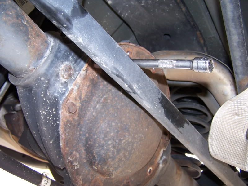
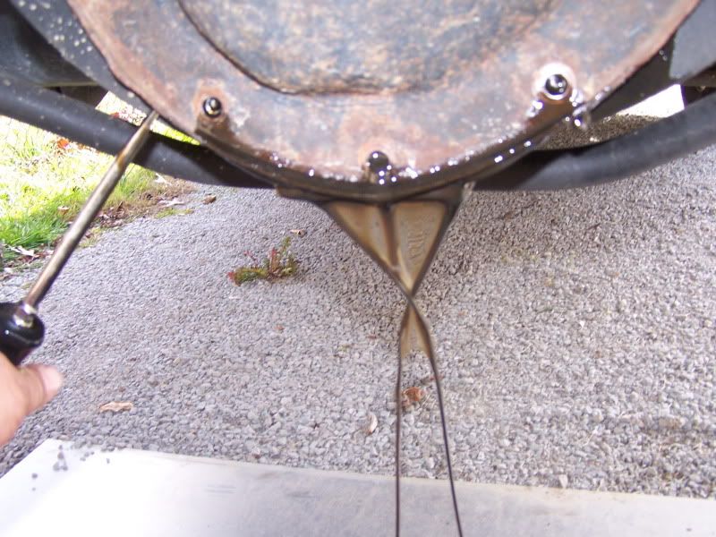
It helps to remove MOST of the bolts, keeping one or two near the top in place so that you can gently pry away the cover making oil removal easier and less messy. There is also a drain plug on the bottom of most TB differential housings, but I decided that since the cover had to come off anyway, why mess with the drain plug — most vehicles don’t have that plug and if it remains in place, factory sealed, it won’t start leaking down the road. (I’ve done this a few times… )
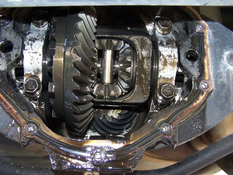
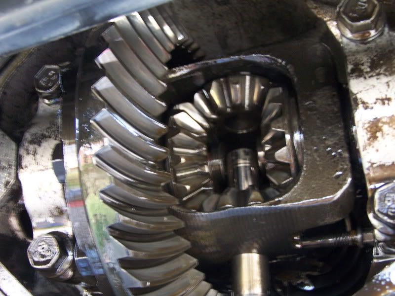
Here is what you find once the cover is removed. This is the differential carrier, and in this picture you can see the large ring gear on the left, the smaller spider gears inside the carrier housing in the center, the center pin that holds the spider gears in place, and also (looking inside deeper) the pinion gear. This is a standard carrier (not a locker or limited slip). If it were a locking rear carrier, it would have a more square shape, as it would house friction clutches and it would also have an additional mechanism (governor) that engages the clutch disks when a wheel spins. No parts “fly out” at this stage of the disassembly, so no fear in pulling the rear cover.
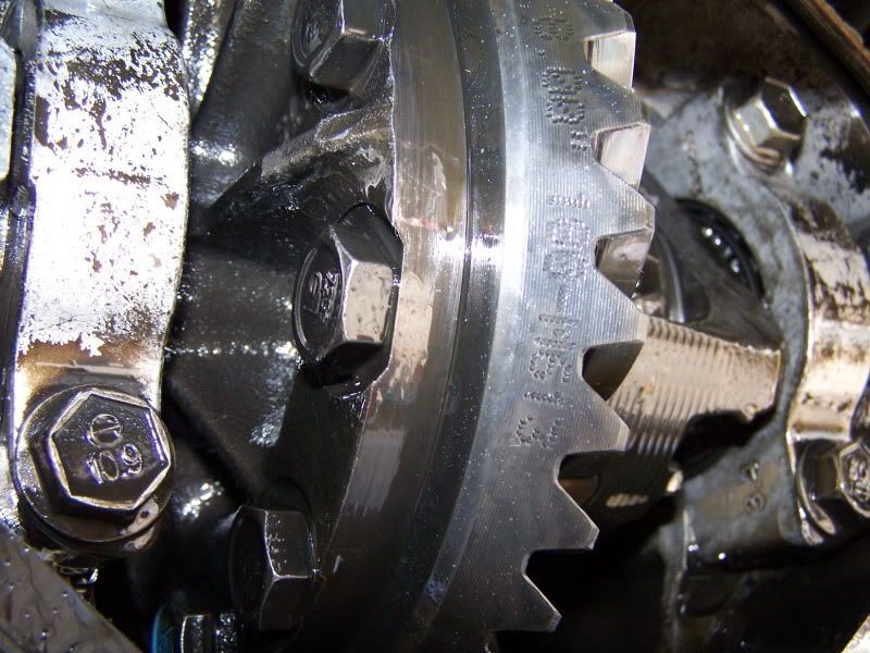
EVERY ring gear (no matter who makes it) will have a set of numbers stamped on it to identify the gear ratio. This is especially helpful if gears have been swapped and/or there is no identifying tag (salvage yard find, etc.) to check. The numbers on the ring gear are the ONLY positive means of identification of the ring and pinion.
The wrench in this picture is placed on the cross pin retaining screw. The screw needs to be backed out enough so that the cross pin can slide out of its bore.
A couple of notes here: (1) The screw is 8mm. (2) It doesn’t have to come all the way out — just enough to slide out the cross pin. (3)The factory recommends replacement of this screw — in the couple hundred rear axles I’ve built, I’ve never replaced one unless it was broken — and that is rare. (4) Angle the carrier to a place where the cross pin will just slide out of the bottom hole — pay attention to the pin as it slides out so that you will be familiar with how it returns when the job is finished.
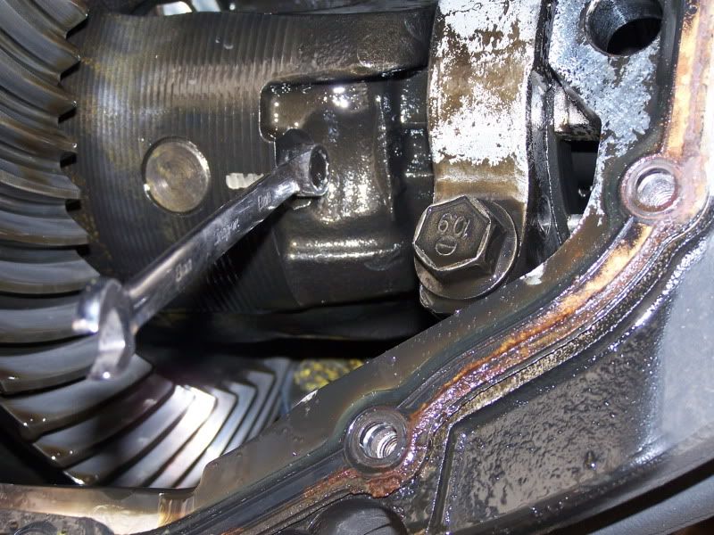
Cross pin sliding out, cross pin retaining screw partially removed. You want to take care here to NOT disturb the alignment of the spider gears (side gears). The ones going up and down are held in place by the cross pin. The ones on each side are held in place by the axle shafts. IF you simply pull the cross pin, and slide out the axle shafts, everything will slide right back into place when you are finished. IF you make the mistake of rotating ANYTHING during this process, you will have to re-install the spider gears, as they will twist right out of the carrier.
Don’t fear if this happens, it is not the end of the world. Each spider gear on the cross pin also has a “shell” (sort of a bearing surface that is a formed washer) behind it that goes with the gear. Make sure they are in place with the gears — they “stick” with the oil that is on them. To re-insert spider gears, insert the top gear about half a tooth, spin the axle shaft, which “rotates” the gear into place almost opposite the open “window” in the carrier (the place where you are working), then insert the opposite spider gear and rotate both gears at once until they line up again with the bore holes for the cross pin. This may take a try or two if you have never done it — sort of a puzzle where all the pieces have to go together at the same time.
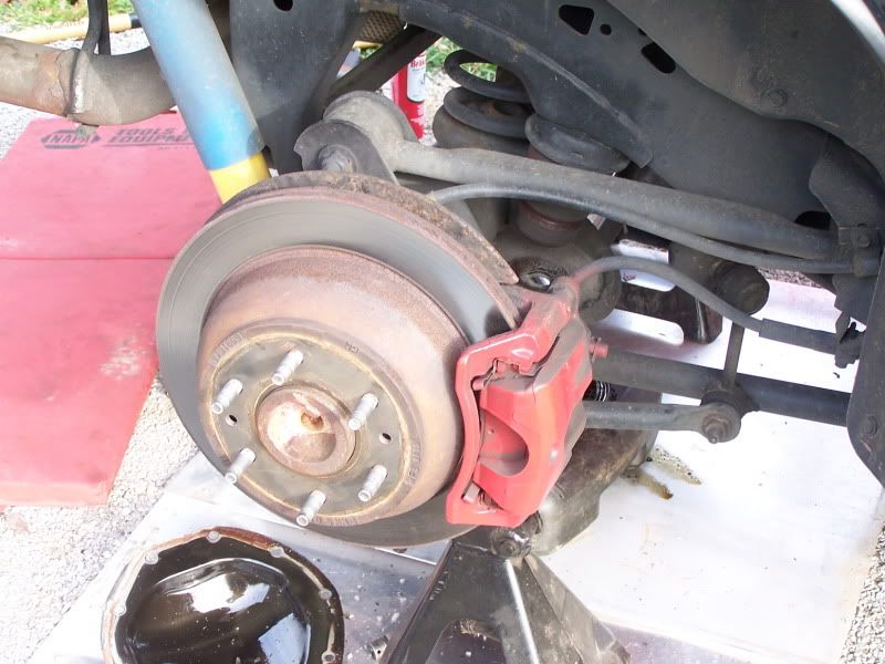
Let’s move outboard to the brakes.
Here is the rear axle passenger side brake setup. They are the same on both sides. The “red” stuff in the picture is what needs to be removed first (I’ve painted my caliper and bracket).
Reaching around behind the caliper, there are two bolts holding the caliper (the part that presses the brake pads against the rotor, which is the part that spins). Remove these with a 13mm wrench or socket. TIP: loosen BOTH bolts before you remove one, as that will stop the caliper from rotating around and giving you problems when you try to loosen the second bolt.

Here is a rear view of the same bolt.
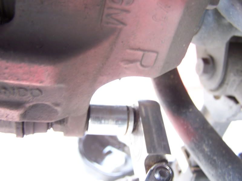
Once the bolts are both out, the caliper can slide right out of the bracket, leaving the brake pads still in place on the rotor.
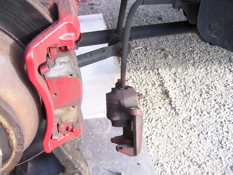
There are then two additional bolts that have to be removed to take off the bracket. These are 18mm and will take a bit of force to remove. I used a large breaker bar. Remember, “lefty-loosey == righty-tighty”.
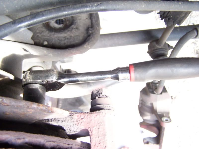
Once both bolts are out, the caliper bracket can be removed giving access to the rotor, which pulls right off the axle.
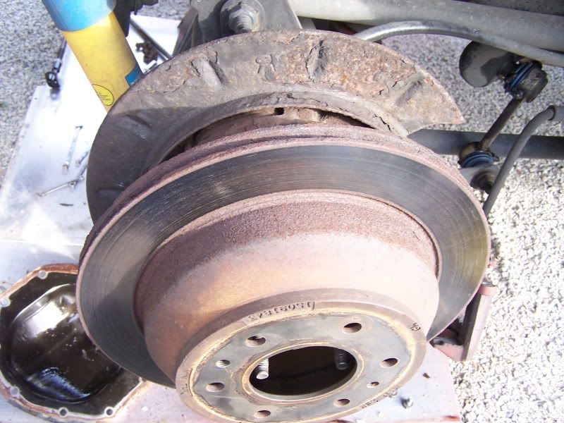
Once the rotor is pulled, you will see the emergency brake pads that rest (and push) against the inside of the rotor. Replace these if they are rusted or worn. I had a set on hand, but mine were in great condition, so I left them in place.
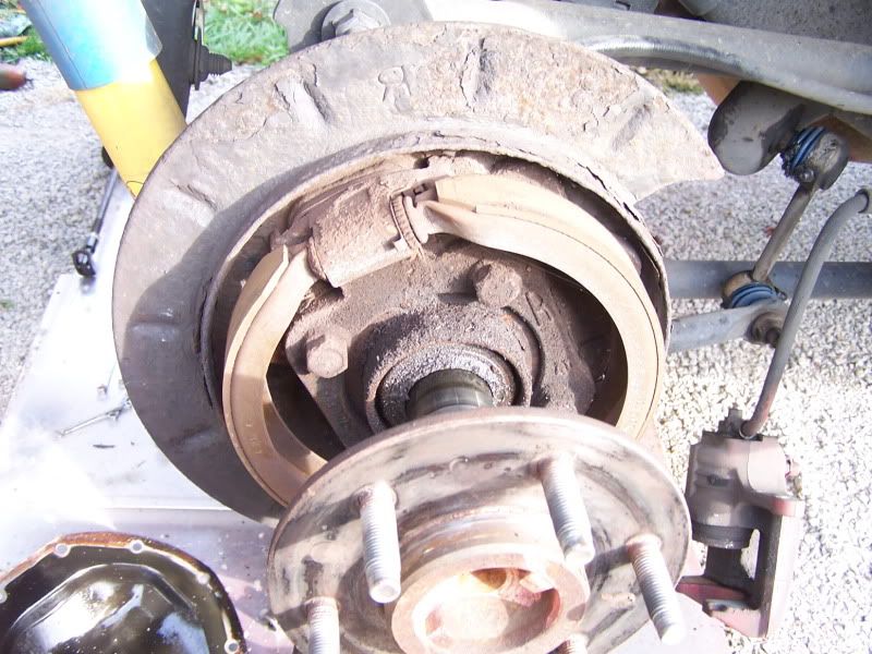
My rotors were worn thin and rusted, however, so I replaced them with NAPA ultra-premium parts.
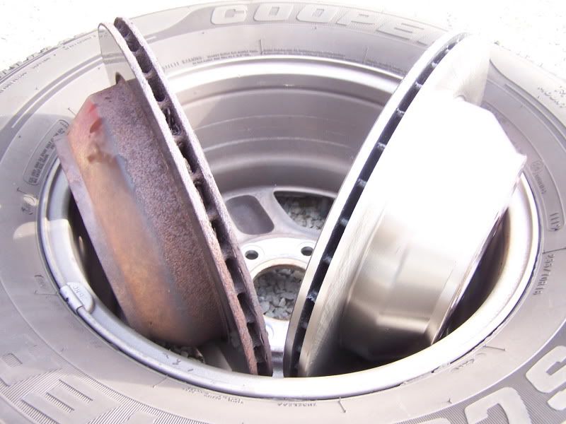
Let’s remove the axle shafts.
To start, push IN on the ends of the axles (push on the lug nut area) and REMEMBER — DON’T ROTATE THE AXLES! The axles will slide right in, about 1/2″ with the cross pin removed.
And, yes, it is NORMAL for axle shafts to move in and out a bit. They will have around 1/8″ in and out play when everything is installed correctly. Any more movement than this and you want to check for axle stretch or twist from spinning out and/or bad C-clips (see next photos).
Now, with each axle shaft pushed inward, the c-clips will be evident between the spider gears — and easy to remove. (sorry for the bad picture, my camera didn’t want to focus that deep into the carrier)
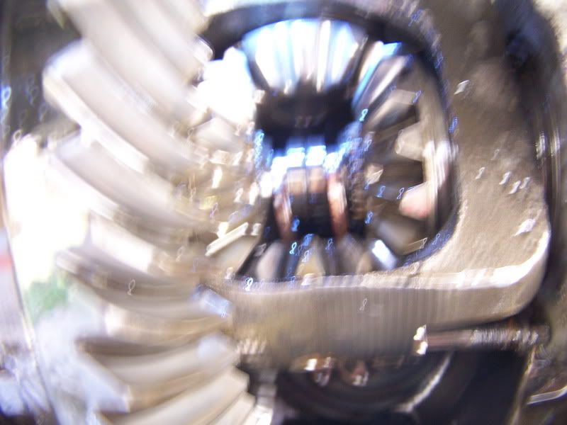
I use a magnet to pop out the c-clips — and yes, that is ALL that holds your axles in place.
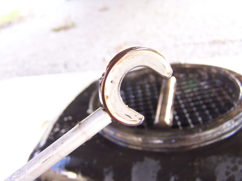
Now, the axle shafts can be slid out of the housing. Expect some oil to drain from the axle housing tubes.
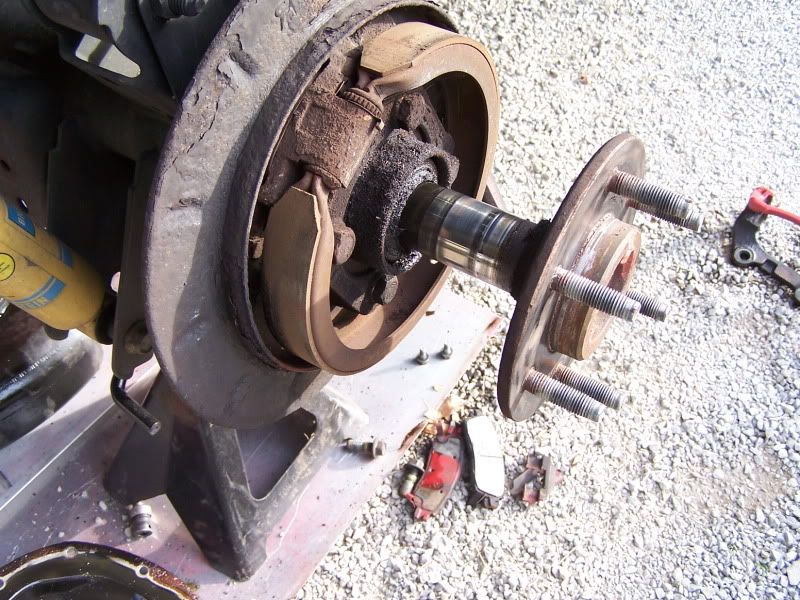
Once removed, you will see the rear axle seal. Yes, my seals are leaking. I have 95K miles — they are DUE for replacement. I pop out the seals before pulling the bearings. Though there are a few different tools that will work, usually a screwdriver applied to the edge of the seal (or driven in to the gap between the seal and the axle housing) will suffice to pop them out of their bores. Don’t worry about destroying the seals. They MUST be replaced anyway.
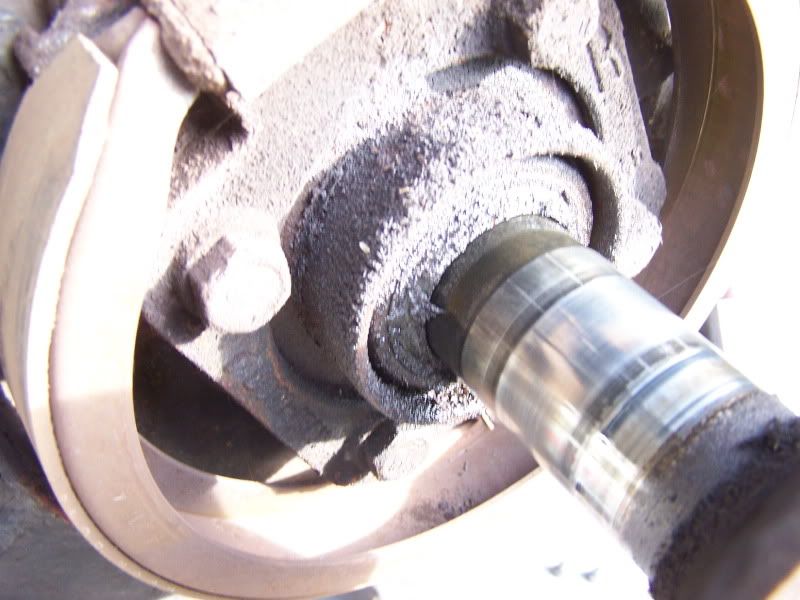
In this picture, note the hot spots on the axle shaft in the area where the bearing rides. It should not be brown and discolored at all — just shiny. IF you have actual gouges in this area, there are replacement bearings that are built to remedy the problem by letting the bearings ride outboard of the standard position. These specialty bearings cost more than the standard replacement units, but they also have a built in seal that deals with the modified placement. They install in exactly the same manner as the stock versions, with one caveat — be careful of the built in seal.
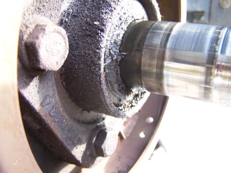
Here is the bearing itself, still in the axle housing. It is pulled out using a specialty puller on a largish slide hammer. Don’t even try to do it another way unless you have access to dealership-level tools. There IS NO OTHER WAY, so get the proper puller.
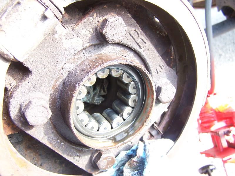
Puller, with bearing and seal removed.
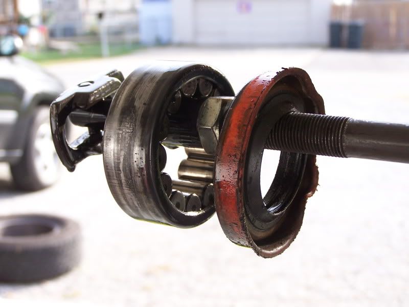
Is your arm sore from slamming the slide hammer yet?
It takes a LOT of force, and a LOT of blows with the hammer to get the bearings to slide out. That is NORMAL. If the bearing just falls out, you have PROBLEMS.
Let’s install the new bearings.
I didn’t take a lot of pictures of the re-install, because for the most part, it is a reversal of the removal.
Clean up the area where you are working with brake cleaner spray. I also take this opportunity to clean out the inside of the differential with brake cleaner spray. Make sure that you don’t have a lot of chips, etc. If so, you need gear repair, which is another topic for another thread. Clean up everything with towels so that it is dry before finishing re-assembly.
Starting with a new wheel bearing, find a suitable driver to press on the outer edge of the bearing that will allow you to tap the bearing into the bore with a soft-hammer (I used a brass hammer and a large socket. A piece of pipe, a block of wood, etc. can be used.) Drive the bearing all the way into its bore (helps to check the depth before you remove the old bearings) and make sure it is seated. The sound it makes as you drive it in will change when it is fully seated (sort of gets to be a dull thud).
I usually grease my axle bearings and seals with a good moly suspension grease before sliding in the axle shaft. The bearings are lubricated with gear oil from the differential, but I like the additional protection of the grease until the oil finds its way to the ends of the axle shafts.
Install the new axle seal. Tap it into place with a seal install tool or with a mallet (carefully, around the edges). As far as seals go, this one installs easily compared to some.
Wipe down the axle shaft and slide it back into its bore — taking care to not mess up the seal or to move the spider gear out of place — it will slide right in. You will want to inspect your axle shafts before you replace them. Look for obvious signs of twisting, especially near the splines — that is the area where they usually break.
Once both axle shafts are pushed back into their bores, re-insert the c-clips and spread the axle shafts outward from the inside of the carrier. Just push with your fingers and they will slide right out.
Re-install the cross pin into the spider gears, taking care to keep the small hole for the retaining screw lined up and in the proper place. Then slide the retaining screw back into its bore and tighten it. It is a small screw, so don’t go hog wild with torque
. About 8-10 foot pounds is more than enough (see my thread on torques in the rear shock area).
Now, you can rotate everything to make sure it moves freely and is back in proper positing.
Re-install the rear cover for the differential, and fill the axle with the gear oil of your choice by opening the fill port, which is located on the passenger side of the differential housing, just above the web, on the front side of the housing. That port takes a 3/8″ square drive (just use an extension on a ratchet wrench) to open and close. You can use thread sealer on it once you replace it. I re-used the factory seal for the differential cover. It didn’t leak. If you choose to not re-use the seal, you can purchase another seal, and/or just use silicone sealer and a bare housing and cover. Make sure you clean everything well in either case.
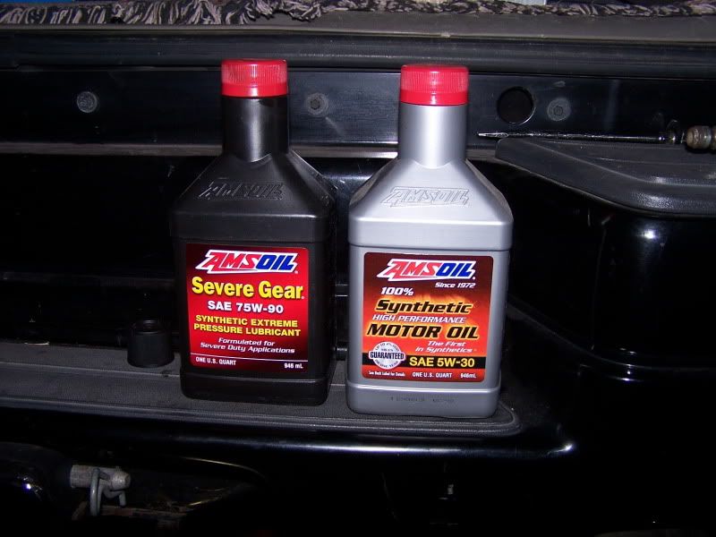
Fill with gear oil until it just dribbles out of the hole with the axle level.
I prefer AMSOIL.
Now, re-install the rear brakes, starting with the rotors, which slide right over the axle shafts. MAKE SURE you clean EVERYTHING brake related with brake cleaner spray. The oil from packing and/or from your hands will cause hot spots that will later make noise and cause early brake failure.
Install the caliper bracket. Tighten both bolts
Install the brake pads into their respective spots.
I tool the liberty of painting my brackets and calipers while they were apart. I just used Rustoleum Professional paint. No fancy paint is required for street-driven vehicles. I’ve not found that regular paint burns off of calipers and brackets.
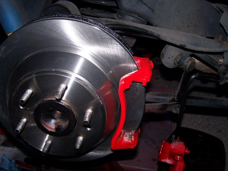
On the calipers, you must return the caliper pistons to their home position before you can slide the calipers over the new brake pads, which are much thicker than the ones you replaced (if you are installing new pads, that is). I use a tool designed for the job. You can also use a c-clamp or large pliers. Make sure you push evenly, so as not to cock the piston in the bore. Also make sure you don’t tear the rubber seal. If done this way, no bleeding of the brakes is needed — BUT — you must GENTLY press the brake pedal a few times before even testing the brakes to seat everything into position correctly. The first couple of tries, the pedal will go to the floor. Make sure your master cylinder is full of DOT 3 brake fluid (changing fluid is recommended, but not covered under the scope of this write up).
Re-install the wheels, and you are finished with the job.
New rear axle bearings, new rear brakes, smooth ride!
 It helps to remove MOST of the bolts, keeping one or two near the top in place so that you can gently pry away the cover making oil removal easier and less messy. There is also a drain plug on the bottom of most TB differential housings, but I decided that since the cover had to come off anyway, why mess with the drain plug — most vehicles don’t have that plug and if it remains in place, factory sealed, it won’t start leaking down the road. (I’ve done this a few times… )
 Here is what you find once the cover is removed. This is the differential carrier, and in this picture you can see the large ring gear on the left, the smaller spider gears inside the carrier housing in the center, the center pin that holds the spider gears in place, and also (looking inside deeper) the pinion gear. This is a standard carrier (not a locker or limited slip). If it were a locking rear carrier, it would have a more square shape, as it would house friction clutches and it would also have an additional mechanism (governor) that engages the clutch disks when a wheel spins. No parts “fly out” at this stage of the disassembly, so no fear in pulling the rear cover.
 EVERY ring gear (no matter who makes it) will have a set of numbers stamped on it to identify the gear ratio. This is especially helpful if gears have been swapped and/or there is no identifying tag (salvage yard find, etc.) to check. The numbers on the ring gear are the ONLY positive means of identification of the ring and pinion.
 The wrench in this picture is placed on the cross pin retaining screw. The screw needs to be backed out enough so that the cross pin can slide out of its bore.
A couple of notes here: (1) The screw is 8mm. (2) It doesn’t have to come all the way out — just enough to slide out the cross pin. (3)The factory recommends replacement of this screw — in the couple hundred rear axles I’ve built, I’ve never replaced one unless it was broken — and that is rare. (4) Angle the carrier to a place where the cross pin will just slide out of the bottom hole — pay attention to the pin as it slides out so that you will be familiar with how it returns when the job is finished.
 Cross pin sliding out, cross pin retaining screw partially removed. You want to take care here to NOT disturb the alignment of the spider gears (side gears). The ones going up and down are held in place by the cross pin. The ones on each side are held in place by the axle shafts. IF you simply pull the cross pin, and slide out the axle shafts, everything will slide right back into place when you are finished. IF you make the mistake of rotating ANYTHING during this process, you will have to re-install the spider gears, as they will twist right out of the carrier.
Don’t fear if this happens, it is not the end of the world. Each spider gear on the cross pin also has a “shell” (sort of a bearing surface that is a formed washer) behind it that goes with the gear. Make sure they are in place with the gears — they “stick” with the oil that is on them. To re-insert spider gears, insert the top gear about half a tooth, spin the axle shaft, which “rotates” the gear into place almost opposite the open “window” in the carrier (the place where you are working), then insert the opposite spider gear and rotate both gears at once until they line up again with the bore holes for the cross pin. This may take a try or two if you have never done it — sort of a puzzle where all the pieces have to go together at the same time.
 Let’s move outboard to the brakes.
Here is the rear axle passenger side brake setup. They are the same on both sides. The “red” stuff in the picture is what needs to be removed first (I’ve painted my caliper and bracket).
 Reaching around behind the caliper, there are two bolts holding the caliper (the part that presses the brake pads against the rotor, which is the part that spins). Remove these with a 13mm wrench or socket. TIP: loosen BOTH bolts before you remove one, as that will stop the caliper from rotating around and giving you problems when you try to loosen the second bolt.
 Here is a rear view of the same bolt.
 Once the bolts are both out, the caliper can slide right out of the bracket, leaving the brake pads still in place on the rotor.
 There are then two additional bolts that have to be removed to take off the bracket. These are 18mm and will take a bit of force to remove. I used a large breaker bar. Remember, “lefty-loosey == righty-tighty”.
 Once both bolts are out, the caliper bracket can be removed giving access to the rotor, which pulls right off the axle.
 Once the rotor is pulled, you will see the emergency brake pads that rest (and push) against the inside of the rotor. Replace these if they are rusted or worn. I had a set on hand, but mine were in great condition, so I left them in place.
 My rotors were worn thin and rusted, however, so I replaced them with NAPA ultra-premium parts.
 Let’s remove the axle shafts.
To start, push IN on the ends of the axles (push on the lug nut area) and REMEMBER — DON’T ROTATE THE AXLES! The axles will slide right in, about 1/2″ with the cross pin removed.
And, yes, it is NORMAL for axle shafts to move in and out a bit. They will have around 1/8″ in and out play when everything is installed correctly. Any more movement than this and you want to check for axle stretch or twist from spinning out and/or bad C-clips (see next photos).
Now, with each axle shaft pushed inward, the c-clips will be evident between the spider gears — and easy to remove. (sorry for the bad picture, my camera didn’t want to focus that deep into the carrier)
 I use a magnet to pop out the c-clips — and yes, that is ALL that holds your axles in place.
 Now, the axle shafts can be slid out of the housing. Expect some oil to drain from the axle housing tubes.
 Once removed, you will see the rear axle seal. Yes, my seals are leaking. I have 95K miles — they are DUE for replacement. I pop out the seals before pulling the bearings. Though there are a few different tools that will work, usually a screwdriver applied to the edge of the seal (or driven in to the gap between the seal and the axle housing) will suffice to pop them out of their bores. Don’t worry about destroying the seals. They MUST be replaced anyway.
 In this picture, note the hot spots on the axle shaft in the area where the bearing rides. It should not be brown and discolored at all — just shiny. IF you have actual gouges in this area, there are replacement bearings that are built to remedy the problem by letting the bearings ride outboard of the standard position. These specialty bearings cost more than the standard replacement units, but they also have a built in seal that deals with the modified placement. They install in exactly the same manner as the stock versions, with one caveat — be careful of the built in seal.
 Here is the bearing itself, still in the axle housing. It is pulled out using a specialty puller on a largish slide hammer. Don’t even try to do it another way unless you have access to dealership-level tools. There IS NO OTHER WAY, so get the proper puller.
 Puller, with bearing and seal removed.
 Is your arm sore from slamming the slide hammer yet?
It takes a LOT of force, and a LOT of blows with the hammer to get the bearings to slide out. That is NORMAL. If the bearing just falls out, you have PROBLEMS.
Let’s install the new bearings.
I didn’t take a lot of pictures of the re-install, because for the most part, it is a reversal of the removal.
Clean up the area where you are working with brake cleaner spray. I also take this opportunity to clean out the inside of the differential with brake cleaner spray. Make sure that you don’t have a lot of chips, etc. If so, you need gear repair, which is another topic for another thread. Clean up everything with towels so that it is dry before finishing re-assembly.
Starting with a new wheel bearing, find a suitable driver to press on the outer edge of the bearing that will allow you to tap the bearing into the bore with a soft-hammer (I used a brass hammer and a large socket. A piece of pipe, a block of wood, etc. can be used.) Drive the bearing all the way into its bore (helps to check the depth before you remove the old bearings) and make sure it is seated. The sound it makes as you drive it in will change when it is fully seated (sort of gets to be a dull thud).
I usually grease my axle bearings and seals with a good moly suspension grease before sliding in the axle shaft. The bearings are lubricated with gear oil from the differential, but I like the additional protection of the grease until the oil finds its way to the ends of the axle shafts.
Install the new axle seal. Tap it into place with a seal install tool or with a mallet (carefully, around the edges). As far as seals go, this one installs easily compared to some.
Wipe down the axle shaft and slide it back into its bore — taking care to not mess up the seal or to move the spider gear out of place — it will slide right in. You will want to inspect your axle shafts before you replace them. Look for obvious signs of twisting, especially near the splines — that is the area where they usually break.
Once both axle shafts are pushed back into their bores, re-insert the c-clips and spread the axle shafts outward from the inside of the carrier. Just push with your fingers and they will slide right out.
Re-install the cross pin into the spider gears, taking care to keep the small hole for the retaining screw lined up and in the proper place. Then slide the retaining screw back into its bore and tighten it. It is a small screw, so don’t go hog wild with torque . About 8-10 foot pounds is more than enough (see my thread on torques in the rear shock area).
Now, you can rotate everything to make sure it moves freely and is back in proper positing.
Re-install the rear cover for the differential, and fill the axle with the gear oil of your choice by opening the fill port, which is located on the passenger side of the differential housing, just above the web, on the front side of the housing. That port takes a 3/8″ square drive (just use an extension on a ratchet wrench) to open and close. You can use thread sealer on it once you replace it. I re-used the factory seal for the differential cover. It didn’t leak. If you choose to not re-use the seal, you can purchase another seal, and/or just use silicone sealer and a bare housing and cover. Make sure you clean everything well in either case.
Fill with gear oil until it just dribbles out of the hole with the axle level.
I prefer AMSOIL.
 Now, re-install the rear brakes, starting with the rotors, which slide right over the axle shafts. MAKE SURE you clean EVERYTHING brake related with brake cleaner spray. The oil from packing and/or from your hands will cause hot spots that will later make noise and cause early brake failure.
Install the caliper bracket. Tighten both bolts
Install the brake pads into their respective spots.
I tool the liberty of painting my brackets and calipers while they were apart. I just used Rustoleum Professional paint. No fancy paint is required for street-driven vehicles. I’ve not found that regular paint burns off of calipers and brackets.
 On the calipers, you must return the caliper pistons to their home position before you can slide the calipers over the new brake pads, which are much thicker than the ones you replaced (if you are installing new pads, that is). I use a tool designed for the job. You can also use a c-clamp or large pliers. Make sure you push evenly, so as not to cock the piston in the bore. Also make sure you don’t tear the rubber seal. If done this way, no bleeding of the brakes is needed — BUT — you must GENTLY press the brake pedal a few times before even testing the brakes to seat everything into position correctly. The first couple of tries, the pedal will go to the floor. Make sure your master cylinder is full of DOT 3 brake fluid (changing fluid is recommended, but not covered under the scope of this write up).
Re-install the wheels, and you are finished with the job.
New rear axle bearings, new rear brakes, smooth ride!
