This article is brought to you by BDS Suspensions.

Front Installation
1.Park the vehicle and a clean, flat surface and block the rear wheels for safety. 2. Raise the front of the vehicle and support the frame with jack stands behind the lower control arms. 3. Remove the front wheels. 4. Disconnect the sway bar from the frame (2 bolts per side). Allow the sway bar to hang down. Retain sway bar mounting bolts.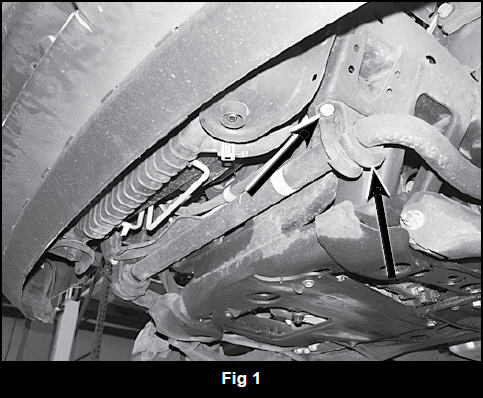 5. Under the hood, locate the driver’s and passenger’s top strut mounting nuts (Fig. 2). Remove the two nuts hold each strut to the frame. CAUTION: DO NOT remove the center strut nut. It is under extreme pressure.
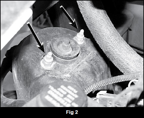 Perform the following steps one side at a time, starting with the passenger’s side.
6. Remove the nut that mounts the strut to the lower control arm (Fig. 3). Retain nut.
7. Using a pitman arm puller or equivalent, remove the strut from the tapered mounting stud. Note: If a puller is not available, taper can be freed by striking with a hammer while prying out on the strut mount. (Fig. 4)
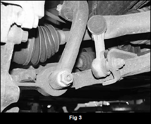
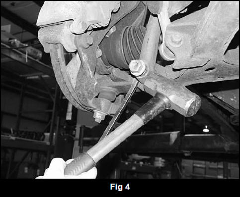 8. Remove the strut from the vehicle.
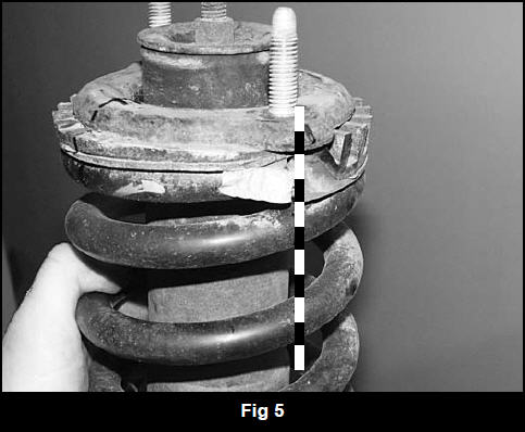
9. Mark the relationships between the top strut plate, coil spring, coil spring mount and strut (Fig. 5). Also mark what side of the strut faces out. The mark on the top plate will need to be transferred to the new top plate provided to ensure the strut is reassemble correctly for proper alignment during installation.
Note: A high-quality wall mounted coil spring compressor (Branick or equivalent) is recommended for the installation. A rod style compressor is sufficient, but use extreme caution and inspect all components for signs of wear and/or fatigue before each use.
10. Compress the spring enough to relieve pressure from the strut rod nut. Remove the nut and remove the top washer, strut plate, rubber/plastic isolator and lower washer. 11. Transfer the mark on the OE top strut plate to the new one. The new strut plate has a third mounting hole in it that will face the outside of the vehicle. Install the OE isolator on the new strut plate by lining up the alignment marks. 12. Install one of the provided stem washers (117300007) and stem bushing (SB14BK) with sleeve (87-1). The protruding sleeve should be opposite of the stem washer. (Fig. 6a / 6b)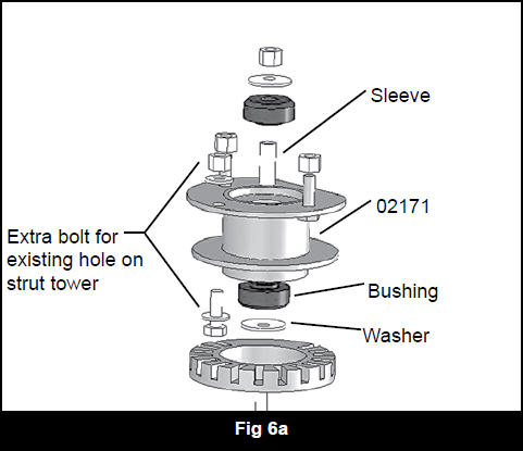
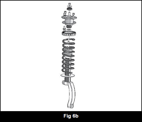 Install the new strut plate/isolator (02171) on the strut and compress the spring enough t 13. o install a second bushing and stem washer. Retain the assembly with the OE nut and tighten until the bushings deform. Note: The bushings should deform to the point when the center crush sleeve bottoms out.
14. Release the spring compressor.
15. Install the modified strut assembly in the vehicle by aligning the studs in the top plate with the original mounting holes. The third hole in the plate will align with an existing hole in the frame. Fasten the strut to the frame with 10mm nuts and 3/8” USS washers on the two studs (Fig. 7). Leave hardware loose.
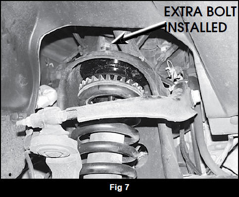 16. Install a 10mm x 30mm bolt, nut and 3/8” USS washers in the third hole (Bolt pack #528). Leave hardware loose.
17. Install the strut on the lower control arm tapered mounting stud and fasten with the OE nut. Snug nut but do not tighten. Final torque will be done with weight of the vehicle on the suspension.
18. Torque the upper 10mm hardware to 35 ft-lbs.
19. Repeat procedure on the driver’s side.
20. With both sides complete, reattach the sway bar to the frame with the OE hardware. Torque bolts to 40 ft-lbs.
21. Install the wheels and lower the vehicle to the ground.
22. Bounce the front of the vehicle to settle the suspension. Torque the lower strut mount nuts to 80 ft-lbs.
23. Check all hardware for proper torque. If installing a #121201 “front only” kit there will be left over hardware provided with the kit.
24. Check hardware after 500 miles. A complete front end alignment is necessary.
Rear Installation
25. Block the front wheels for safety. 26. Disconnect the rear track bar from the driver’s side of the axle. Retain hardware. (Fig. 8 ) 27. Raise the rear of the vehicle and support the frame with jack stands in front of the lower control arms. 28. Remove the wheels. 29. Support the rear axle with a hydraulic jack. 30. Remove the OE rear shocks. Retain shock hardware. (Fig. 8 ) Perform the follow steps on one side at a time, starting with the passenger’s side.
31. Disconnect the upper control arm from the axle. Retain hardware. (Fig. 8 )
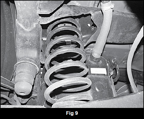
32. Lower the axle and remove the coil spring and upper rubber isolator. (Fig. 9)
 33. Apply loctite to the threads of three 5/16” x 1” bolts (Bolt pack #528) and thread them into the provided coil spring spacer so that ¼” of thread is still showing. (Fig. 10)
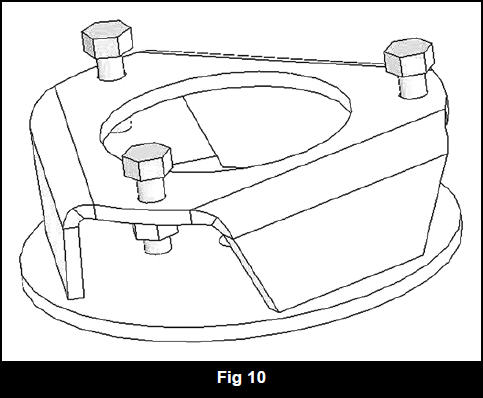 34. Install the coil spring spacer (02172) in the vehicle by aligning the 5/16” bolt heads with the slots in the frame coil mount. Once the bolt heads are in the slots, turn the spacer to lock it in place. Note: The spacer will be loose in the mount. The bolts are only there to hold the spacer in position while installing the coil spring.
35. Install the OE rubber isolator and coil spring in the vehicle. Take care not to over-extend any brake lines.
36. Raise the axle to compress the coil spring enough to reattach the upper control arm to the axle. Fasten the control arm with the original hardware. Leave hardware loose.
37. Repeat procedure on the driver’s side of the vehicle.
38. With both sides complete, install the new BDS shocks with the provided bushings, sleeves and OE hardware.
Torque hardware to 55 ft-lbs.
39. Install the wheels and lower the vehicle to the ground.
40. Bounce the rear of the vehicle to settle the suspension. Install the track bar in the axle mount with the OE hardware. Torque to 125 ft-lbs.
41. Torque the upper control arm bolts to 95 ft-lbs.
42. Check all hardware for proper torque.
43. Check hardware after 500 miles.
Source for this article: http://www.bds-suspension.com/pdfs/011201.pdf
