The New Venture Gear model NVG 226 transfer case is the dual speed, automatic, active transfer case in the Chevrolet TrailBlazer and GMC Envoy. It provides five modes of operation:
- 2 HI
- Auto 4WD
- 4 HI
- 4 LO
- Neutral.
General Operation:
The Auto 4WD position allows the capability of an active transfer case, which provides the benefits of on-demand torque biasing wet clutch and easy vehicle tuning through software calibrations. The software calibrations show more features such as flexible adapt ready position and clutch preload torque levels. The technology allows for vehicle speed dependent clutch torque levels to enhance the performance of the system. For example, the system is calibrated to provide 0-5 lb ft of clutch torque during low speed, low engine torque operation, and predetermined higher torque for 20mph and greater. This prevents crow-hop and binding at low speeds and provides higher torque biases at higher vehicle speeds, to enhance stability.
The NVG 226 requires no clutch shimming. the transfer case control module controls for the wear of the clutch and different clutch torque levels. The software learns adapt ready positions, which are for the correct clutch torque. The learned adapt ready positions vary as the unit wears over its life.
2WD

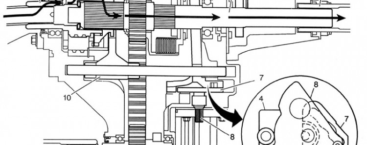
The power flow from the transmission to the prop-shafts when in 2WD.
When the NVG 226 is in the 2 HI mode, the power flows from the transmission to the input shaft gear (1). The input shaft gear is connected to the rear output shaft (5) by the high/low range collar (2). The range collar inner teeth, high speed, are engaged with the input shaft gear (1) high speed position teeth. At the same time the range collar is slip splined to the rear output shaft (5). The rear output shaft delivers the power flow to the rear propshaft (6). The position of the control actuator lever shaft (8) allows no clutch engagement. The shift detent lever (7), which moves the shift rail and shift fork (10), is in the high speed position on the control actuator shaft (8).
4 HI and A4WD

Showing the power flow from the transmission to the prop shafts when in 4HI and A4WD.
In the 4 HI mode, the power flow to the rear propshaft is the same as in the 2 HI mode. To deliver power flow to the front propshaft during the 4 HI position, the transfer control module commands the encoder motor to apply the clutch to a calibrated torque. the encoder motor turns the control actuator lever shaft (8). A brake in the encoder motor holds the control actuator shaft in the full clutch position. The control actuator lever shaft (8) is cam designed and the cam action moves the clutch lever (4). The clutch lever (4) pivots on the control lever picot studs and moves towards the clutch apply plate, to engage the clutch. As more pressure is applied to the clutch apply plate, the clutch disks are compressed. Using inner clutch disks, which are engaged with the clutch hub (3), and the outer clutch disks, which are engaged with the clutch housing, the power flow is delivered to the clutch housing.
The clutch hub (3) is splined to the rear output shaft (5), and the clutch housing rotates on a needle bearing on the rear output shaft (5). The chain drive sprocket is splined to the clutch housing. The power flows from the drive sprocket, through the chain, to the chain driven sprocket. The driven sprocket is splined to the front output shaft (9). The power flow is delivered to the front propshaft through the front output shaft (9).
During the Auto 4WD mode, the power flow is the same as it is in the 4 HI mode. Except during the A4WD mode, the encoder motor rotates the control actuator shaft lever to the learned adapt ready positions. Rotating the control actuator to the carious positions changes the clutch torque level. When a differential of front propshaft and rear propshaft speed is recognized, the transfer case control modules commands for more, or less clutch torque.
4 LO

The power flow through the transfer case when in 4WD and low range.
When shifting the transfer case to the 4 LO mode, it commands the encoder motor to turn the control actuator lever shaft (8) to move the shift detent lever (7), and to apply the clutch. The shift detent lever (7) moves the shift rail and the spring dampened shift fork (10). The shift fork (10) moves the high/low range collar (2) on the rear output shaft (5) splines toward the rear of the transfer case. The range collar (2) inner teeth, high speed, disengage from the input shaft gear (1) high speed teeth. The range collar (2) outer teeth, low speed, then engage in the planetary carrier teeth. The power flow is now from the input shaft (1) planetary teeth to the planetary gears in the carrier. Rotating the planetary gears, which are engaged in the annulus gear, the carrier rotates. The carrier, that is engaged to the range collar, then drives the rear output shaft. Therefore, providing a 2.69:1 reduction to the speed of the rear output shaft. The power flow to the front propshaft is the same as it is in the 4 HI mode.
A neutral position is obtained when the range collar is not engaged to the input shaft gear or the planetary carrier. Neutral position is used for towing the vehicle.
4WD Mode Selector

The NVG 226 transfer case features a rotary 4 mode shift control switch located on the instrument panel. When the ignition key is in the RUN position, the transfer case shift control module monitors the transfer case shift control switch to determine if the driver desires a new mode/range position. At a single turn of the transfer case shift control switch, the lamp of the new desired position will begin flashing to inform the driver that the transfer case shift control module has received the request for a new mode/range position. The lamp will continue to flash until all shifting criteria has been met and the new mode/range position has been reached, or has been engaged. Once the new mode/range position is fully active, the switch indicator lamp for the new position will remain ON constantly. During normal driving situations, the transfer case can operate in the Auto 4WD mode. In the Auto 4WD mode, the transfer case shift control module monitors rear wheel slip speed, based on the inputs from both the front and rear propshaft speed sensors. When the vehicle experiences a rear wheel slip condition, the transfer case shift control module sends a pulse width modulated (PWM) signal to an electronic motor, which is the transfer case encoder motor. This motor rotates the transfer case control actuator lever shaft, applying a clutch pack. This clutch pack is designed to deliver a variable amount of torque, normally delivered to the rear wheels, and transfers it to the front wheels. Torque is ramped up to the
front wheels until the front propshaft speed sensor matches that of the rear propshaft speed sensor. Torque is ramped down to the front wheels. The process would repeat if rear wheel slip is detected again. The NVG 226 transfer case has the added feature of also providing the driver with 3 manual mode/range positions:
- 4HI 4-Wheel Drive high range
- 2HI 2-Wheel Drive high range
- 4LO 4-Wheel Drive low range
The driver may choose to select any of these mode/range positions while driving the vehicle. However, the transfer case will not allow a shift into or out of 4LO unless the following criteria has been met:
- The engine is running.
- The automatic transmission is in Neutral.
- The vehicle speed is less than 5 km/’h (3 mph).
This transfer case also has a Neutral position. A shift to the Neutral position allows the vehicle to be towed without
rotating the transmission output shaft. Neutral position may be obtained only if the following criteria has been met:
- The engine is running.
- The automatic transmission is in Neutral.
- The vehicle speed is less than 5 km/h (3 mph).
- The transfer case is in 2HI mode.
Once these conditions have been met, turn the rotary switch clockwise past the last position and hold for 10 seconds. When the system completes the switch to neutral, the red neutral lamp will appear.
Transfer Case Control Module (TCCM)

The transfer case shift control module uses the VIN information for calculations that are required for the different calibrations used based on axle ratio, transmission, tire size, and engine. The system does not know which calibration to use without this information. When the Vehicle is in the AWD mode, the transfer case shift control module monitors the speed of the front and rear propshafts in order to detect wheel slippage. When wheel slippage is detected, the module applies a clutch pack contained in side the transfer case. This clutch pack is used to lock-in and apply the front propshaft, transferring torque to the front wheels. The clutch pack is applied by a motor/encoder assembly. When slip is no longer detected by the transfer case shift control module, the clutch is no longer applied.
Transfer Case Motor/Encoder

The transfer case Motor/Encoder consists of a permanent magnet (PM) DC motor and gear reduction assembly. It is located on the left hand side (drivers side) of the transfer case. When activated it turns the sector shaft of the transfer case (clockwise or counter clockwise) to shift the transfer case. The Motor/Encoder is controlled with a pulse width modulated (PWM) signal by the transfer case shift control module. This circuit consists of a driver on both the Motor A and Motor B circuits. The encoder motor is bi-directional to allow the motor to shift the transfer case from 2HI or 4HI to NEUTRAL and 4LO positions.
Transfer Case Encoder
The encoder is mounted to the transfer case motor/encoder assembly and is replaced as an assembly. The encoder converts the sector shaft position (representing a mode or range) into an electrical signal input to the transfer case shift control module. The module can detect what position the transfer case is in by monitoring the voltage returned on the encoder signal circuit. This voltage translates into AUTO, 2H, 4H. NEUTRAL. and 4L or in transition between gears.
Transfer Case Motor Lock
The transfer case motor lock is used to provide a 2H, 4H, and 4L lock-up feature. When the lock circuit is energized, the transfer case encoder motor is allowed to turn. When the transfer case is placed 2H, 4H, or 4L the motor lock circuit is de-energized and the lock is applied. This assures that the transfer case remains in the current gear position until a new gear position is requested. When AUTO is selected the motor lock remains applied until an adaptive mode (torque is applied to the front propshaft) is required. During an adaptive mode the motor lock circuit is energized and the motor lock is released, enabling the encoder motor to turn and apply or release torque at the front propshaft.
Transfer Case Speed Sensors
There are three speed sensors on the automatic transfer case (ATC), two on the rear output shaft and one on the front output shaft. Each speed sensor is a permanent magnet (PM) generator. The PM generator produces a pulsing AC voltage. The AC voltage level and number of pulses increases as speed increases.
Vehicle Speed Sensor
One of the two on the rear output shaft is the vehicle speed sensor (V SS) input to the powertrain control module (PCM). The PCM sends this information to the transfer case shift control module via the Class 2 Serial Data bus.
Rear Propshaft Speed Sensor
The transfer case shift control module converts the pulsating AC voltage from the rear transfer case speed sensor to a rear propshaft speed in RPM to be used for calculations. The rear propshaft speed can be displayed with a scan tool.
Front Propshaft Speed Sensor
The transfer case shift control module converts the pulsating AC voltage from the font transfer case speed sensor to front propshaft speed in RPM to be used for calculations, and to monitor the difference between the front and rear sensor speed. It is also used in the AUTO (Adapt) mode of operation to determine the amount of slip and the percent of torque to apply to the front axle. The front propshaft speed can be displayed with a scan tool.
Service 4WD Indicator Lamp
The SERVICE 4WD indicator is an integral part of the cluster and cannot be serviced separately. This lamp is used to inform the driver of the vehicle of a transfer case system malfunction. The SERVICE 4WD indicator is controlled by the TCCM via Class 2. The SERVICE 4WD lamp will only illuminate if the TCCM can electronically verify there is a malfunction. This means that a mechanical failure of the front disconnect would not be identified by a SERVICE 4WD indicator.
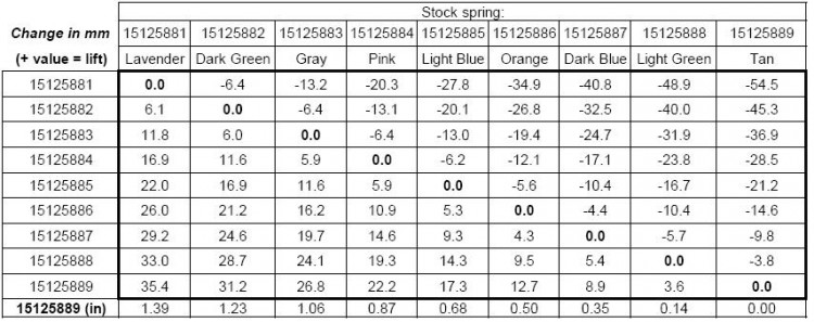
![tb-springs[1]](http://thedownings.us/offroad/wp-content/uploads/2016/01/tb-springs1.jpg) All the calculations were easier to do in metric, so I only converted the bottom row to inches for your reference. The conversion from mm to in is to divide by 25.4.
Consider this your disclaimer. Use this information at your own risk. A higher spring number WILL produce a stiffer, rougher ride. If you lift your vehicle too far, you could break something. Always make sure you triple check your calculations first.
All the calculations were easier to do in metric, so I only converted the bottom row to inches for your reference. The conversion from mm to in is to divide by 25.4.
Consider this your disclaimer. Use this information at your own risk. A higher spring number WILL produce a stiffer, rougher ride. If you lift your vehicle too far, you could break something. Always make sure you triple check your calculations first.


